- français
- English
Altium to Allegro using TELESIS
Altium to Allegro using TELESIS
- Telesis Format
- Edit the schema
- Assign Footprints, Values and Device Types
- Generate the netlist with Output Job
- Send zipped Files to ACI
1.Format
 $PACKAGES
FOOTPRINT!COMMENT!DESIGNATOR
...

$NETS
NETNAME; DESIGNATOR.PIN_NUMBER DESIGNATOR.PIN_NUMBER ...
...

$End
|
Where the signification of the fields is:
- $PACKAGES starts the paragraph that declares all components.
- FOOTPRINT is a name defined in ACI-CAO Footprint catalogue.pdf
- COMMENT must precisely define each physical Component e.g. all resistors of the same value may share the same COMMENT but only when they are in the same footprint. The value parameter can be inserted by using =VALUE. Syntax for more elaborate info (='GRM21BR70J225KA01L' + '!' +VALUE)
- DESIGNATOR is R1, C1, U1 ... Please follow the recommendation on Wikipedia. (Testpoints my exceptionally be more explicit in the character limits specified above.)
- $NETS start the definition of the connections NETNAME is the name attached to wires in the schematic (e.g., GND, VCC, 10V, Reset, etc.) or and automatic generate name such as NETJ1/3. Differential nets should have _N _P as postfix.
- After the semi-colon follows a list of nodes that are on the same net. A nod is composed of a DESIGNATOR that is followed by the PIN_NUMBER. PIN_NUMBERS should be as defined in the datasheet of the component. If they do not correspond with the ACICAO catalog we map them while reading the netlist.
NOTE: FOOTPRINT and DESIGNATOR must not contain spaces or other characters then [A-Z][a-z][0-9] and '_'. They are case insensitive and must not start with a number.
2.Schema
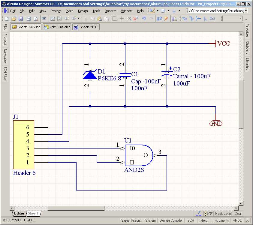
The schema specifies the connections that show up in the $NETS paragraph of the 'TELESIS' netlist.

3.Assign Footprints, Values and Device Types
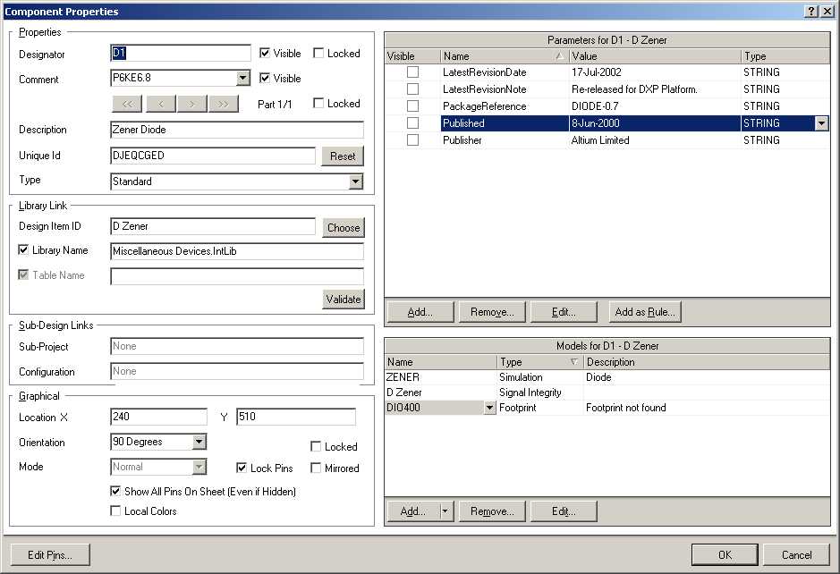
Use the Component Properties dialog box to assign or check the information of the $PACKAGES paragraph of the netlist.
Footprint!Comment; Designator
The first column contains the Footprint. Naming must follow the ACI-CAO ACORT footprint catalog.
The second column contains the value of the 'Comment' field that describes the component. Ex. 0.125W - 1k. The values of the Parameters Section can be used in the Comment field using the =ParameterName construct.


4.Generate the netlist with Output Job
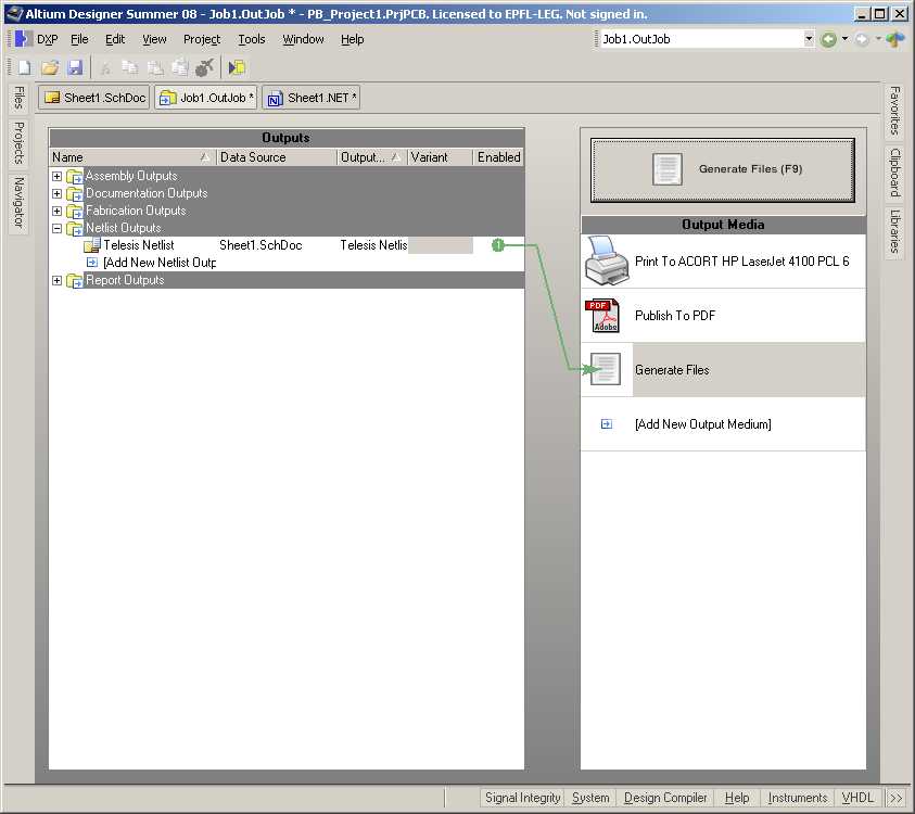
To configure the Output Generator proceed as follows:
- Right-click on the project name in the Projects Window
- Add New to the Project
- Select Output Job File
- Click on 'Add New Netlist Output' and choose Telsis. (if it is not available it must be installed)
- Configure Folder Structure as shown below.


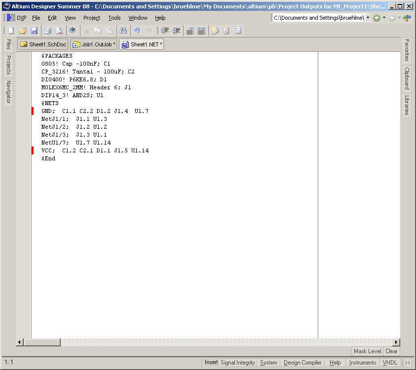
You should get a netlist of the following format:
If the window does not show up you must set the 'Open generated outputs' in the Advanced section of the Folder Structure settings. (Right-click on Folder Structure and select Properties)

5. Send zipped files to ACI
Zip the project with the 'Project Packager' included in Altium. It strips of all temporary files.
- Right click on the project name in the Projects Window
- Select 'Project Packager'. This opens a Wizard Window.
- Hit twice 'Next' as standard options are mostly OK.
- Send the zip file to Peter.Bruehlmeier@epfl.ch

- Ce wiki
- Cette page
