
- français
- English
The prototype
Welcome to the prototype page! Here you’ll find all the information necessary to build, understand and use our prototype.
Below is a list of essential components you’ll need to build the prototype. Prices are also indicated. However, note that these prices may fluctuate depending on where you buy them.
- Arduino Uno R3: Microprocessor needed to control the prototype.
Where to get it: http://shop.boxtec.ch/arduino-uno-p-40155.html
Software needed: http://arduino.cc/en/Main/Software
Price: CHF 27.80
- LCD Arduino Shield: Screen to display the results.
GitHub with schematics, PCB, how to use it and how to build it: https://github.com/fakufaku/LCDShield
Price: CHF 20
- XPE Series Cree Blue LED: Emits a blue light at 475nm. Used to quantify the fluorescence of the sample via GFP excitation.
Where to get it / Specifications: http://www.superbrightleds.com/moreinfo/high-powered/xpe-series-cree-led/325/
Price: $ 12.95
- 3mm Red High Flux LED: Emits a red light at 630nm. Used to quantify the turbidity of the sample.
Where to get it / Specifications: http://www.superbrightleds.com/moreinfo/component-leds/3mm-red-high-flux-led-70-degree-viewing-angle-5500-mcd/361/
Price: $ 0.25
- Light To Frequency Converter – TSL235R: Photosensor that measures the intensity of light that goes through the sample.
Where to get it: https://www.sparkfun.com/products/9768
Datasheet: https://www.sparkfun.com/datasheets/Sensors/Imaging/TSL235R-LF.pdf
Price: $ 2.95
- 2x P-channel Mosfet Transistor: Pull-up, PMOS transistor
Where to get it: http://akizukidenshi.com/catalog/g/gI-00034/
Specification: http://akizukidenshi.com/download/2sj471ds.pdf
Price: ~ CHF 2 each.
- 2x Plastic Biconvex Lenses: To concentrate the light coming from the sample onto the photo detector for a higher precision of counting.
Where to get it: http://www.knightoptical.com/stock/optical-components/uvvisnir-optics/lenses/plastic-lenses/
Price: ~ CHF 7 each.
We’d like to thank Valentin Simeonov at ENAC for providing these for free.
- Resistors, wires, solder, button etc…
You’ll need a 100 ohm, a 47 ohm and two 10 ohm resistors
Price: Roughly CHF 5
___________________________________________________________________________
Total price: ~ CHF 85
Let’s note that this price can still be further reduced by, for example, choosing a cheaper Arduino microcontroller.
Build it step by step
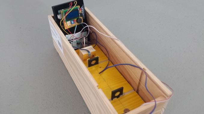
Our prototype is contained in a wine box. The idea is to have a prototype easily reproducible so you can use any closable box.
To build it, follow the following instructions.
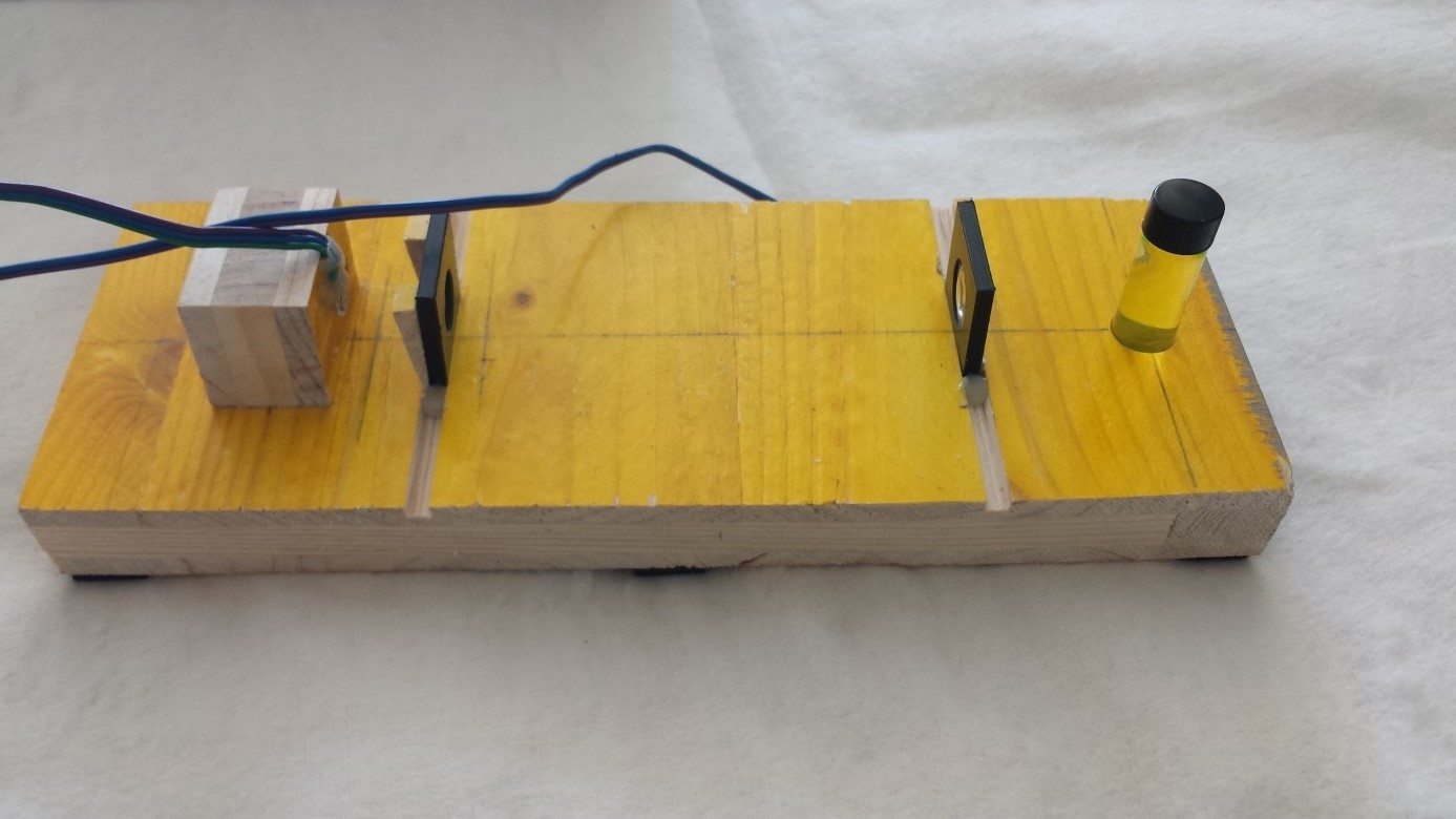
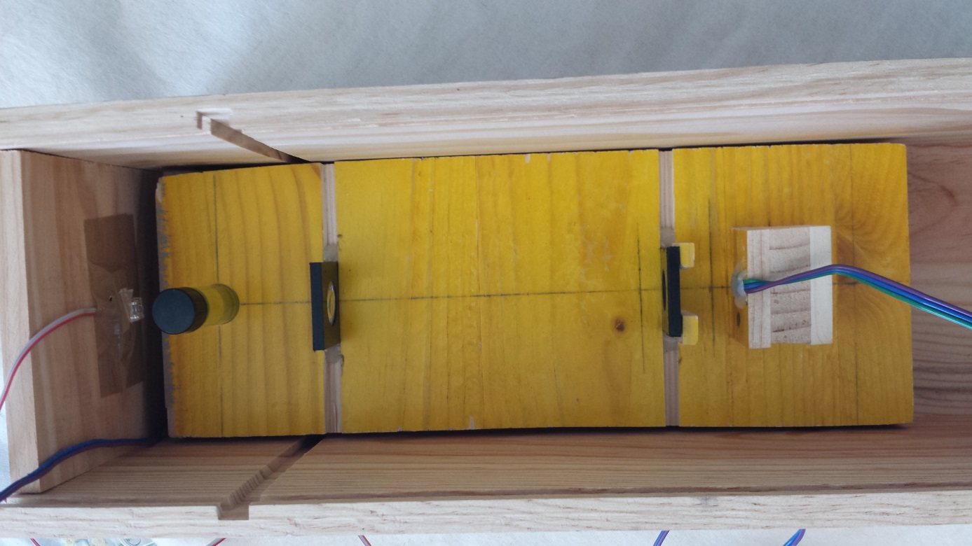
Step 1: Make the optical part
To make this part, you need a wood board where you have to foresee:
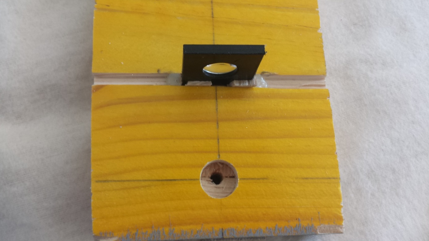
- A socket of 15 mm in diameter where you can put the future sample that we want to test.
- A square piece of wood to stick the photosensor on.
- Two trenches for two biconvex lenses that focus the light on a target point.
The distance between the two lenses should be optimal for the focusing of light. By experimenting, we concluded that this distance was 12,2 cm.
Step 2: Add the photosensor and the blue LED
For the photosensor, you have to stick it on the square block of wood after connecting its anode and cathode to the wires which will be connected themselves to the circuit.
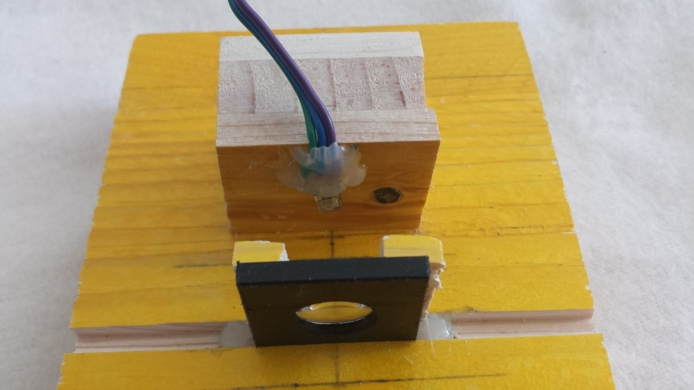
For the blue LED, inside the socket, you have to make another hole that allows the light of the LED to go through. Then after connecting the anode and cathode as before, you stick the LED in order to have the light passing through the hole.
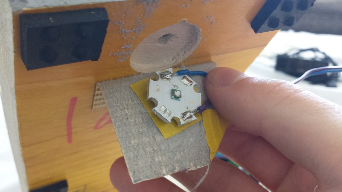
Step 3: Add the red LED at the end of the box
Connect one wire for the cathode and one for the anode and stick the LED with tape. Be careful not to hide the LED with the tape. One way to do this is to cut a square inside the tape and put the LED in this square.
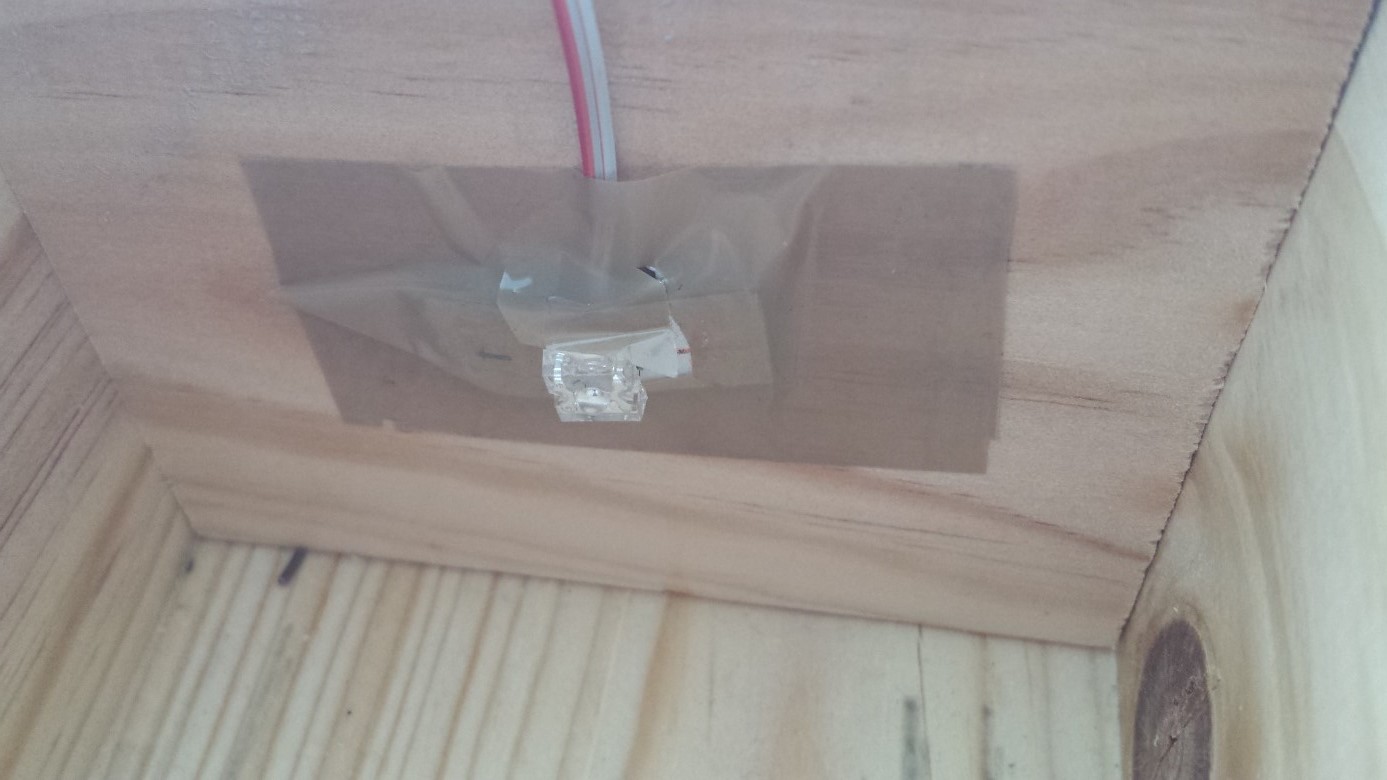
Be sure that the red LED is correctly aligned with the sample and the lenses of the board inside the box so they're at the same height. Place the board as close as possible to the red LED.
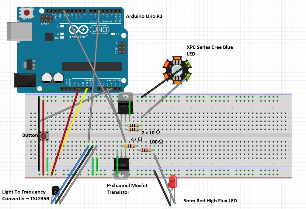
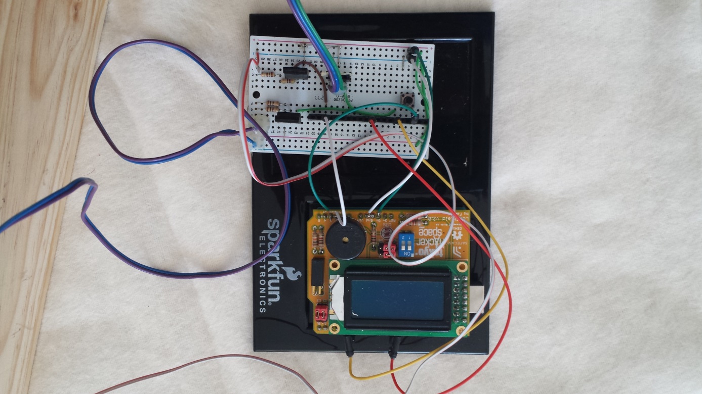
Step 4: Make the circuit
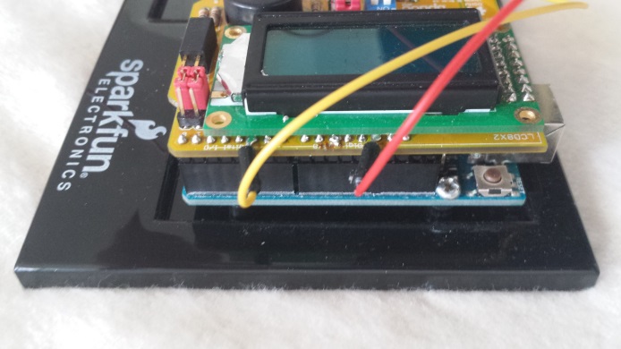
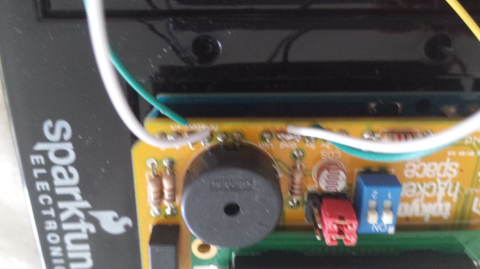
The following sketch explains the wiring required. Note that the LED screen is not seen on it and that it’s an interface between the arduino and the circuit. However, when you incorporate the LCD screen on the Arduino board, you will have to solder the cables for the different pins onto the LCD board and then reconnect it to the circuit in the same place. This modification can be seen on the following pictures.
Code
To use the prototype, you’ll need to use this Arduino code so you can start measuring! Comments are added to the code so you can understand it and modify it if you need to. The program is uploaded onto the Arduino microcontroller (via a USB cable) so it can function autonomously without the computer. However, you still need to keep the computer connected to power the microcontroller; a future prototype design will be able to run on a battery.
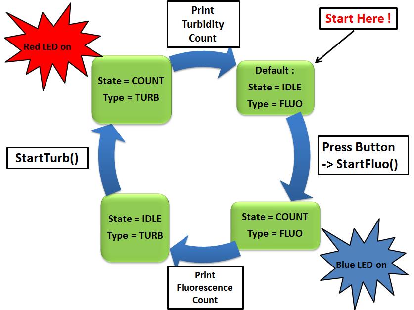
In short, the program setups the screen and LEDs and then awaits the push of the button before starting the measurement processes. On the push of the button, the blue light will turn on (for 30 seconds) in order to measure the fluorescence of the sample. Once the measurement is done, the blue light is switched off, the result is printed on the screen and the system then pauses for 3 seconds before turning the red light on (for 300 milliseconds) to measure the turbidity. Once the turbidity measurement is done, the red light switches off and the result is printed on the screen. The system then awaits the push of the button before starting the aforementioned process again. Let’s note that the time lengths can be changed in the code if necessary. Here’s a diagram illustrating the code’s loop function that controls the above process:
Global view
Once all these steps are done, assemble everything together and you'll have (hopfully) functioning prototype! To use it, upload the code, place the sample in the socket, close the box and press the button to start measuring.
This is what you should get:
Here you can see a little video giving a brief explanation about the prototype:
https://www.youtube.com/watch?v=pABDwnhZBLE
- Ce wiki
- Cette page