
- français
- English
Part II: Physical behaviour
This page is dedicated to the analysis of the ShapeOp tool, which is a library for static and dynamic geometry processing for optimisation under constraint. For more information on the library, refer to http://shapeop.org/

Domain of application
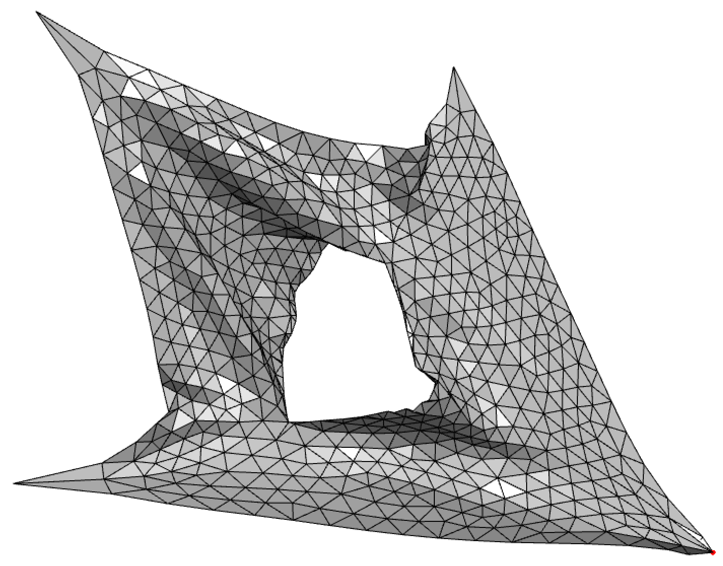
For the purpose of testing I will mainly use a flat sheet of 568 vertices created from one of the sides of a cube. The side was then remeshed multiple times using the smallest edge as target length. The result is a flat square mesh made up of roughly equilateral triangles arranged in no particular order. We can see this mesh on the image at the top of this article, coloured in green, cut near the upper right corner and stretched from top left to bottom right.
Constraint exploration
Closeness constraints
This sort of constraints is useful for placing vertices at desired places. In particular we can fix certain vertices and set a handle on others to be able to move them around at will.
In MeshCut we can select any set of vertices and fix them using a closeness constraint with a relatively big weight. The weights in ShapeOp are a relative measure to be able to assign importance to specific constraints. Therefore the fixed vertices are given the highest weight to ensure they really do remain motionless.
To allow for interactivity, it is possible to set some handles on vertices. These are, in the likes of fixed vertices, assigned a high weight with a closeness constraint. But unlike their counterparts, the importance of respecting the mouse motion is lower, so we set the weight to half of the maximum range.
Edge strain constraints
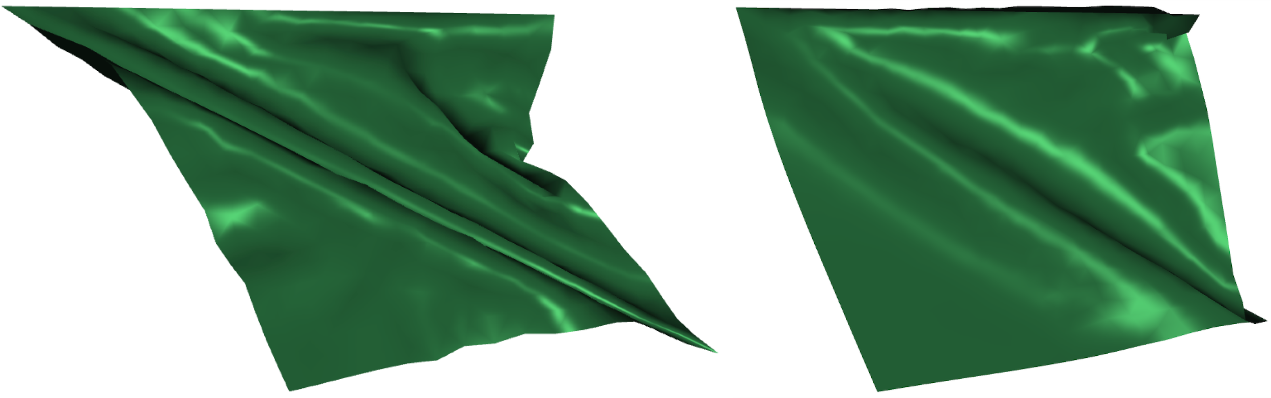
For the simulation of a plausible physical behaviour such as paper for example, we can set constraints on edges to keep their length close to their original value. On the following image we can see on the right how the sheet behaves when pulled to the right with the top vertices fixed. Notice how the material seems to remain rigid compared to the image on the left.
Triangle strain constraints
Instead of restraining the edges to a set length, we can drive triangles to retain their original shapes. While the result is not too dissimilar to using edge strain constraint, we notice that in this case the material is more souple, which is a reminder of cloth fabric.
An indicator of the difference between these two instances is the way the left border bends. On the left it does so toward the inside of the object while the more stiff sheet on the right appears to bend in the opposite direction.
Area constraints
 For a material to be able to be bendy, area constraints are very useful. They try to preserve the area of each triangle, which makes it possible to stretch edges independently. By setting the minimum and maximum ratios with regard to the initial area, one can make the surface stretch inward or swell outward.
An example of inward stretching can be seen on the right. The sheet has a cut at its center, and we can see it reaching outward as if it was compelled to expand; this is because the sheet itself is shrinking and pulling on all its fixed extremities.
This effect is obtained in iterative steps, at one of which the upper bound of the area constraint is lowered and the solver positions reset.
It is also possible to combine constraints together such that we obtain more complex material properties. In the following example we used both triangle and area constraints to model a solid yet stretchy material. To be able to see both aspects we introduced a lateral cut at its center, fixed three of its corners and pulled on the last.
 Notice how wrinkles form around the cut and extremities extend, just as we would expect from a material such as a rubber sheet for example.
Bending constraints
 Some materials are easier to fold and bend than others. Consider for example the difference between paper and a sheet of steel. Obviously steel will oppose more resistance to bending than paper, and this can be modelled with bending constraints.
On the right, we can see a tube mesh that is cut along the side and fixed near the cut. Bending constraints with a maximum range of zero are then applied all over the mesh and we can observe it unfolding into a flat sheet over the iterations. We notice also that unlike we would expect in the real world, the mesh unfolds by first taking a trip to the bottom. This is because of the connectivity of the mesh. In fact, it is not quadrilateral but regularly triangular with all diagonal edges directed in the same way. The orientation here is critical, as during the unfolding each bend pushes toward being flat, to the bottom first in this case.
Rectangle constraints
When manipulating quadrilateral meshes it is useful to use rectangle constraints to preserve the squareness of each face. This is particularly interesting when applied to a tiled square with a particular connectivity, for example hinged tessellated meshes. We will talk about this in the 'Special cutting patterns' page.
Angle constraints
To be able to move faces relative to each other around hinges, setting angle constraints is quite handy. We will see in the 'Special cutting patterns' page how they can be applied to manipulate hinged tessellated meshes.