
- français
- English
Part I: Cutting mesh plugin
Cutting primitives
Definitions
Cutting primitives include the operations performed on single instances of elements, like a single cut on an edge or a split of one vertex.
A "cut" is similar to a hole in a surface. It is defined by two or more boundary edges that were introduced from point to point.
When the mouse cursor moves too fast with respect to the precision of the recorded movement, a "jump" can occur. A "jump" typically spans multiple faces and edges, but always more than two in the case of faces, and one in the case of edges.
Two-step cutting
This first instance of the MeshCut plugin will be split into two parts, namely cutting at edges and then opening the cut.
More precisely the cutting part intends to actually split at individual edges to create an opening in the topology. The second part will allow to open a bigger cut defined by consecutive one-edge cuts by splitting at connecting vertices.
Cutting along a single edge
 When clicking on the mesh, one can select an edge to be cut. Obviously it is more probable that the user clicks on a face rather than an edge (or vertex); this allows to compute the distance from the hit point to edges on the face and to discriminate between them.
Cutting is done by duplicating the selected edge and its halfedges, taking care of all properties and pointers to neighbouring elements.
The last thing to do is to set the outer halfedges as boundary and the cut is complete.
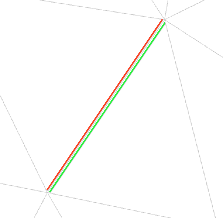
We can see on the image on the right a triangle mesh being cut at a single selected edge, where the red edge is the initial one and the green edge is the new, added one. Note that at this point these two edges are boundary edges, which means there is effectively a hole between them.
Connecting cuts
By grouping edges in left and right side, we can split a vertex that connects cuts in two and redistribute the edges to their attributed vertex side. Again the pointers to neighbouring elements need to be taken care of accordingly.
User interaction
Selecting edges
 Edge selection is convenient for discriminatory or precise work on a mesh without modification to the mesh geometry. The user can (de)select individual edges for later cutting, which is particularly appropriate for joining curves or closing loops for example.
Drawing a path
The mesh can be cut more precisely by first drawing a curve on its surface. It can be performed using the mouse by clicking and, while holding, tracing a path through the surface. The path actually connects edge crossing points whenever the cursor traverses from a face to another.
Because of time constraints I decided to add a functionality to the drawing tool, namely to be able to clamp the drawn curve to the mesh. Implementation for this tool is easier than the one for real curves as we will se in the 'curve drawing implementation' section. It also allows to have an intermediate tool between single edge selection and curve drawing.
Interface feedback
Selected edges get coloured in red for the user to see which of them cutting will be applied to.
When drawing a curve, the path (composed of all hit points) is displayed as a red series of lines that appear just like the path under the mouse cursor. As soon as the button is released and the curve applied to the mesh, the resulting path is set as selected and coloured in red.
Curve drawing implementation
Implementation of a curve cutting tool can be separated into smaller components based on particular cases. Here I will go through the details of the components I have already covered in code.
Discrete world
Like most of the computing world, this plugin has to deal with discretisation of representation of the concepts it uses.
When sweeping over the mesh with the mouse, the registered path is not continuous but rather a sequence of points that, when you link them up together, represent an approximation of the real curve we have drawn.
Furthermore, the mesh on which we want to apply this curve is discrete by itself. In our case composed of triangle or polygon faces, it lets us apply a cut by creating new edges between existing or newly created vertices.
In this implementation, we choose to make the application of the curve to the mesh correspond to the intersections of that curve with the existing edges of the mesh.
Mouse interaction
The first point in the discrete path is registered when the user clicks on the mesh with the mouse. A series of points are then registered whenever OpenFlipper signals that the mouse has moved. Each of the registered points are in 2D on the viewer and then projected to the target mesh, from which we can find the hit point in 3D and index of the hit face. We can then compute proximity elements such as closest vertex and closest edge; these last elements will be important for what follows.
When the mouse button is released or the mouse gets out of the mesh, the registered path is deduced and applied to the mesh.
Intersecting the mesh
 For simplification let us consider triangle meshes only for the moment.
Assume there is at least one registered point on each face the mouse hovered over. We can skip all the points until the last one on the first face, then make a segment with the first point on the next face and compute the intersection with the segment defined by the respective closest points on both sides of the crossed edge using Thales' intercept theorem. The intersection point and edge index are saved to an array for the splitting phase. This is done recursively until the path has been covered completely.
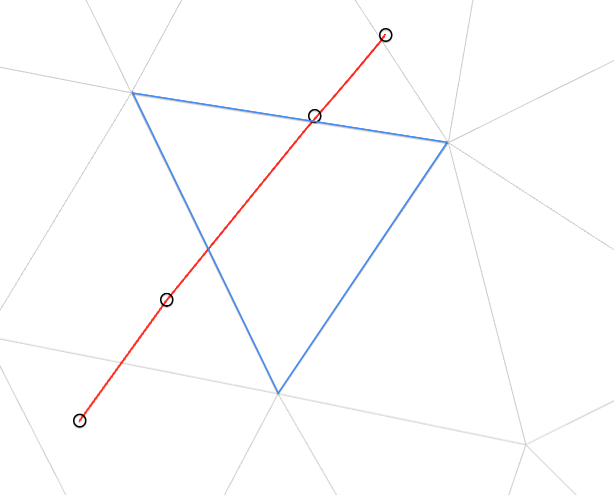
Unfortunately in practice our assumption doesn't always hold. There is an obvious case for which the recorded mouse movement is not precise enough and yields points that are further apart than would be necessary for the method of computing the intersection on both sides of the same edge. Consider for example the triangle mesh image on the right where small black circles represent the recorded points and the red line is the deduced path. We can see that the outlined triangle (in blue) does not have a path point on it. I will call this event a 'jump'.
To make up for the missing points, a possible strategy is to iteratively search for the next intersection and continue from that point.
Searching for the next intersection
Let us define the segment designated by the current recorded point and the next one, which is outside of the face the current point lies on. They are the end points of a 'jump'. Let us call that segment an outgoing segment, because its starting point is inside the face and its end point is outside of it.
We now want to find the intersection of that segment with one of the edges of the triangle. To do that it is useful to first project the segment onto the plane defined by the face, next we can iterate over the face's edges and check for an intersection with a slightly modified version of the method found in the book 'Graphics Gems' 1st ed. at p.304 under the title "Intersection of two lines in three-space". This method allows to verify whether a segment intersects, is parallel to, is collinear to or does not intersect another segment, which is particularly useful as we will see subsequently.
Once the intersection has been found, we can mark it as previously done and continue on to the next intersection.
Remember that this is a recursive process, so we must correctly identify the next point in order to find all the intersections between the two points of the jump.
The case of infinite intersection
If we consider the method for intersecting a segment with another we can see a problem with the recursive approach of our problem. Once we have found the first intersection point of a 'jump', the next time we try to find one the intersection will sometimes (based on order of edge around face iteration and position of previous intersection) fall back onto that same intersection which we just entered the new face from. This causes the algorithm to loop indefinitely on the same point without ever getting to the end of the 'jump'.
A way to get around this situation is to push the new starting point inside the new face in order to avoid finding the same intersection twice. This is done by shooting lines from the face centroid to their vertices and finding the first intersection of our 'jump' line with one of these. The newly found point is then set to the new path point and we can finally recurse correctly.
The edge cases
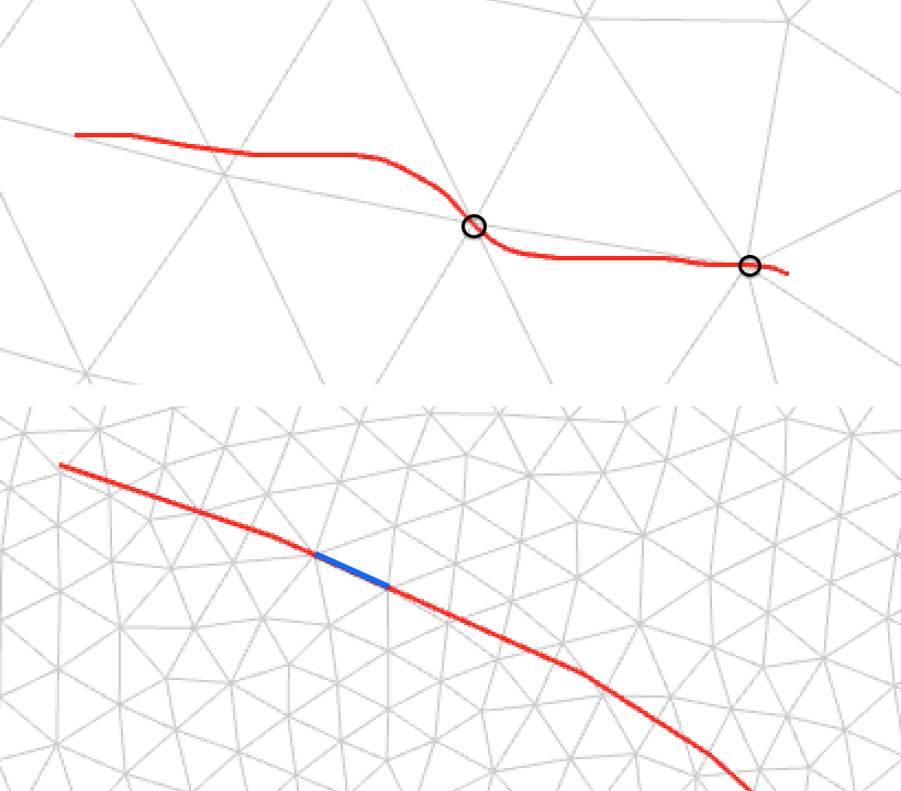 We can see two special cases on the pictures on the left. The first one is when the path goes directly over vertices, like shown under the small black circles of the top image. The challenge here is, instead of marking an edge and a crossing point, to skip the splitting that follows and only select the edge between the vertex and the exit point on the face. At the moment of writing I still haven't completely managed to handle this case, but will return to it if time permits. A possible solution would be to combine the drawing tool's approach with the clamping functionality, which I will describe in the next subsection.
The bottom image shows a normal path in red and a particular slice in blue denoting a superposition of the drawn curve and an edge of the mesh. This is a particular case of the first one, where this time the edge is under a 'jump'. Similarly to the first one, this case needs more investigating at the time of writing and I will address it if time allows.
Clamping tool
 As mentioned in the drawing path subsection of the user interaction section, there is a clamping tool implemented that fills the gap between the single edge selection tool and the curve drawing tool.
The way it works is simple, the closest vertices to hit point are registered when drawing a curve on the mesh. Each time the closest vertex on the path changes, the algorithm checks whether it is near the same edge as the point just before it. If it is, simply register this vertex in an array for later application, if not we have to perform the same deduction of path as for the curve drawing method when 'jumping'.
Under development
At the time of writing there are some functionalities that still require further refinement such as the handling of edge cases.
Note also that the complete cutting base of the plugin, namely cutting at a single edge, connecting cuts as well as most utility functions are written as template functions and handle both triangle meshes and polygonal meshes. Although I made the simplifying hypothesis of considering triangle meshes only, the latter will make it easier to expand to polymeshes also.